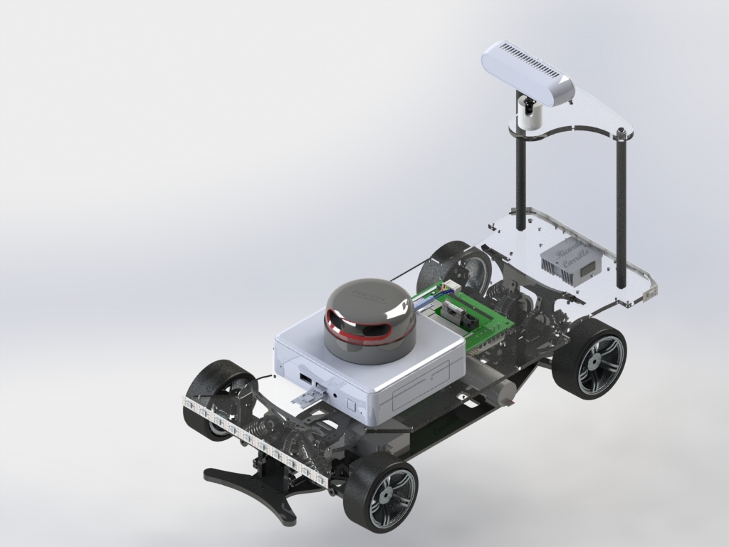
Autominy Core
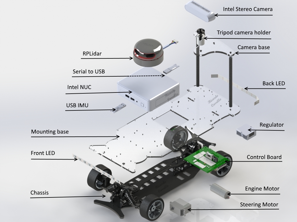
The base Hardware of our car, processes all the algorithms on an Intel NUC CPU and provides the basic configuration to run the car autonomously. The design was thought to be easy maintenance, in our experience in the classroom with the students, the car is not exempt to collide at high speeds with other cars or the walls, therefore, the car can be easily repaired by changing each of the separated modules and spend more time on programming, and testing than repairing hardware. The camera holder is 20cm over the ground to allow the car to see the track ahead and process the images in order to execute task as localization, lane detection and obstacle detection. The base platform of the Autominy is shown on Fig. 1 it consist of the following components:
| Item | Description | Additional information |
|---|---|---|
| Chassis | Xcite RC car chassis (1:10) | Datasheet |
| Steering | Adafruit Servo Motor with Analog feedback | Datasheet |
| Engine | Faulhaber motor with encoder | Datasheet |
| Lidar | RPLIDAR A2M8 360° one beam Laserscanner | Datasheet |
| Infrared Stereo Camera | Intel Real Sense D435 | Datasheet |
| IMU | BOSCH BNO055 USB Stick | Datasheet |
| Computer | Intel NUC8I5BEK | Datasheet |
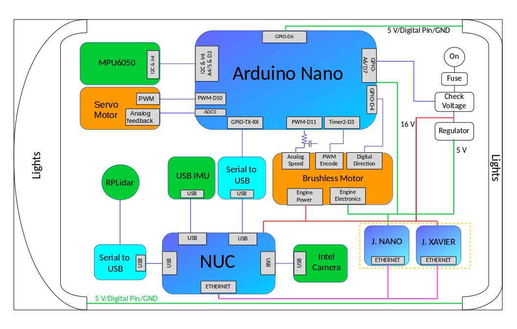
| Control Board | Developed at FU Berlin | The board contains: Arduino Nano, IMU MPU6050, Voltage Sensor, Fuse |
| Voltage Regulator | Converts battery voltage to 5V | Maximum current is 10A |
| LEDs | LED strips: 11 at the back, 10 at the front | Datasheet |
Architecture
Autominy is mainly based on two separated processing modules: one controller board with a microprocessor (Arduino nano) and an Intel NUC computer. The controller board, is a four layer PCB where the Arduino controller and an additional IMU is installed, the board is the main responsible for the following tasks:
Battery Voltage Checker
As main source to power the Autominy we recommend to use a 14.8V Lipo battery with 4000 mAh. Due to the nature of the battery type, it cannot discharge below 13v or the battery can develop several damage in the cells, based on our experience in the lab with dozens of students, we know that being aware of such delicate parameter is not always guaranteed, therefore the controller board checks the voltage of the battery at the start and during the activities. This task is developed by a voltage divider, the arduino and a relay. In order to turn on the car, it is necessary to press the push button for 5 seconds, time on which the arduino calculates the average of the measurements and diagnose the battery, if the voltage is enough, the middle frontal and back LED changes from red to green and the software of the car starts. During the activities the car turns automatically off when the voltage is under 13v.
Chassis Sensor data acquisition
The Arduino reads the information given by both motors: Engine and Steering. Engine: The DC motor has an incremental encoder which allows us to know the velocity and the direction of the schaft, the pulses are read by hardware interruptions on the Arduino. Steering: The servo motor has an analogical voltage output which is read by an analog input and transformed to normalized values between -1 and 1 with a previous calculated calibration. The information is sent through serial communication to the NUC computer using a binary protocol in order to publish topics in the ROS environment on the NUC.
Voltage distribution
In the Autominy two main voltages are used: Battery voltage (above 12v) and 5v. The board distributes the battery voltage to the regulator which converts it to 5v, battery voltage also source the Engine power and the NUC computer. Optionally the Jetson Xavier receives voltage from the board as well. The board receives the 5v from the regulator and distribute it to the Arduino, Steering, and Engine electronics. Optionally in the Autominy Nano it also feeds the Jetson Nano from NVIDIA.
Control of the chassis
The Arduino communicates with the NUC through serial protocol, an ongoing interchange of data is happening all the time with the arduino to execute the desired commands published on the topics which control the Engine, Steering and LEDs.
The second module is the NUC Intel computer which is the main processor of the Autominy, it handles the data coming from the controller board, LIDAR, a Bosch USB IMU and the Stereo Camera to drive autonomously. A diagram with the basic architecture of Autonomy can be observed on Figure 2.